Application Spotlight
Roll Your Own Voltage Regulator
Need to generate a 3V supply from a 5V input, but don't have the right LDO handy? Our latest "Application Spotlight" article shows how to build simple, low-cost voltage regulators out of a handful of common components.
Deriving multiple power supplies from a single input is a task common to most embedded systems. In this article, we explore some simple circuits for stepping down a 5 volt rail to 3 volts.
In most cases, the obvious solution is to use a 3 volt LDO − it's a simple integrated solution. However, there are times when using an LDO may not be the best or lowest cost choice. You may need to build a quick prototype in the lab without the right LDO handy. Or you may be looking to drive cost out of a design and would like to save the 40¢ or 50¢ for the integrated regulator. In either case, here are some ideas for linear step-down circuits.
Shunt Regulator
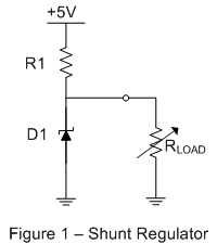
One simple method to generate a lower voltage rail from an input is the shunt regulator. Shown in Figure 1, the shunt regulator uses a 3 volt zener diode and resistor to generate 3 volts to drive the load.
Though simple and inexpensive, this circuit has several drawbacks. First, it does not actively regulate the voltage delivered to the load. Any variation in the diode's reverse voltage with load or temperature will be passed through directly. Also, this regulator always consumes worst case power, regardless of the behavior of the load.
If the circuit powered by the regulator drops to a low power state (effectively increasing RLOAD) the current that was being consumed by the load is delivered to the zener diode instead. The shunt resistor always carries the maximum current for the load. This characteristic means the shunt resistor and zener diode must be rated to handle the maximum power expected in the circuit. As a result, the bias resistor R1 must be sized according to the following equation:
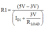
where ID1 is the minimum required bias current for the zener diode and RLOAD is the minimum load resistance.
The benefit of this circuit is cost: the resistor and zener diode together cost less than 10 cents. For the right application, this circuit is the least expensive way to get the job done.
Buffered Shunt Regulator
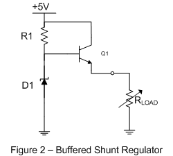
We can improve the shunt regulator's efficiency by adding a voltage follower to the output as shown in Figure 2.
The voltage follower buffers the output of the shunt circuit and drives the load, reducing the variation in the shunt currents by roughly the β of the transistor. For this circuit, if the load drops to a low power state, the collector current through the output transistor decreases. The shunt circuit can be designed to use a low bias current to reduce the overall power consumed by the regulator. For this design, the value of R1 is given by the following equation:
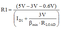
where ID1 is the minimum required zener bias current, βmin is the minimum current gain of the transistor, and RLOAD is the minimum load resistance. For a given value of R1, the short-circuit current of the regulator is given by:
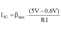
Although an improvement over the basic shunt regulator, this circuit still has its drawbacks. It still does not provide any active regulation of the output voltage, so any load transients could cause the output voltage to move temporarily beyond acceptable limits. The bias voltage will also move with temperature, causing the output voltage to vary across operating conditions.
From a cost view, however, the buffered shunt still looks pretty good. The lower power rating of the bias resistor and diode save a couple of cents, but the extra transistor adds 5 cents or so. Altogether, the buffered shunt costs about 15 cents.
Series Regulator
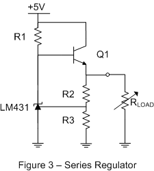
By replacing the zener diode with an adjustable zener shunt regulator (such as an LM431) we can implement a series regulator as shown in Figure 3.
This circuit improves on the buffered shunt by incorporating feedback to allow active regulation of the output voltage. As the load current changes, the resistor divider will mimic that change and adjust the control voltage to the shunt regulator, which modifies the bias level of the voltage follower to compensate.
The zener shunt regulator adjusts its current to keep its reference voltage at its nominal value, which in this case is 2.5 volts. If the feedback voltage is higher than 2.5 volts, the shunt will sink more current and reduce the amount of base current to Q1. This in turn reduces the emitter current delivered to the load and the feedback resistor string, reducing the feedback voltage. For this regulator, the output voltage delivered to the load is given by:

The design value for R1 is similar to that shown for the Buffered Shunt Regulator with the addition of some extra load current due to the resistor divider. The new equation for R1 is given by:

where ILM is the minimum current required by the LM431. This simple series regulator is similar to an integrated LDO, but without features such as thermal protection. At a cost of about 25 cents, it is worth considering for applications that do not need some of the more advanced LDO features.
Summary
In this article, we examined three basic circuits for stepping a 5 volt supply down to 3 volts. Hopefully we have demonstrated that even the most simple applications present opportunities to trade off performance, cost, and convenience. The proper choice for a given design depends on the goals of the designer and the intended use of the end application.

